Gosh darn it, it seems to function quite well.
My ramblings about my private world of electronics and music, motorcycles and movies
Hayling Island

Tuesday, September 20, 2022
Friday, September 2, 2022
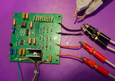
Milli ohm meter getting warmer ...
So the aforementioned PCB arrived back, have assembled.
I had to play with resistor values and so on, but now I have a circuit that will pump 500mA through the device under test. There is a x100 amplifier which boosts up the voltage developed across the DUT to a suitable voltage for an Arduino 10 bit ADC to convert.
Friday, August 19, 2022
Yet Another Transistor Matcher - my version
I found an article or a blog post on how to match transistors with a bit of slick interface. Matching transistors is pretty essential for exponential converters and ladder networks for filters on synths. Now you can do it manually with precision measurements, or you can use this circuit to show a quite groovy method.
I adapted it slightly - I have a whole drawer of old LF13331 analogue switches which I have used with an Arduino to sequence through, and a x1000 amp on the back side. It takes up to 8 NPN or PNP transistors, and plots their Vbe on a scope. Now since I am an old git and I like to be able to see the components I am soldering, I am using pretty much all PTH components. How quaint, I hear you say.
So, I have a small KiCad PCB made by Seeed Studios:
The net effect is in this bit of a scope picture. I have AC coupling on so the tops of each step slope slightly in this picture - but you can easily see how you can select pairs of transistors with similar characteristics. 2 and 4 in this case are really close, 6 and 8 quite close and so on. It's surprising how quickly the levels change with a finger on the tranny - so it takes a bit of time to settle once the transistors are put in the sockets.
And it works! Quite pleased to be honest.
Saturday, July 23, 2022
More Kicad stuff ...
Playing more with KiCAD these days. I designed a milli-ohm meter (it's not original - it's another of Rod Elliots designs, but I have done a schematic and laid it out. Quite pleased with the results. KiCAD is slowly getting easier to find my way around - clearly a lot of hot key work needed to make it slick.
Saturday, July 9, 2022
Archer 2779601 Power Supply
So I have an ancient (1986) bench power supply from Tandy in the US, which has a spot on my bench. I have other power supplies for specific reasons, but this beast is 20v, 2.5A with a current limit and seems to survive lots of abuse. I have used it for decades.
It does suffer from some ageing components though, and I dug around in the paperwork from my stay in the US and found the manuals for it. Someone on T'Internet might find them useful ...
Please find PDFs of the manual (with schematics and wiring diagram) and the assembly instructions, bill of materials and so on.
Friday, June 10, 2022
Yet more Minibrute
So last year I bought a minibrute ... made it kind of work. I did some more work on it recently - replaced the big connector between the analogue and digital boards. That helped enormously with the stability, and functions working. There were a couple of bits left over - the pitch bend didn't work, the LFO doesn't seem to do anything and the aftertouch was flaky.
I just spent a happy couple of hours sorting out the aftertouch and the pitch bend, and I have now worked out that the issue with the LFO is the waveform selection switch - which is completely open circuit. There is a Mouser part (Alpha?) that seems to measure up to fit, so I will be ordering one in the near future. In the meantime I just wired across the switch to give a sine wave LFO waveform - and now, things are a whole lot better.
I've done a knob job on it - the sliders were looking very tatty, and I paid a silly amount of money for some replacement rotary knobs. So now it looks like this ...
Wednesday, April 20, 2022
Tuesday, April 5, 2022
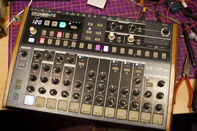
Arturia DrumBrute ...
So, I was attempting to repair a bit of music electronics yesterday evening. Fault in the power supply somewhere - one of those overload ones, where you turn it on, the lights flash briefly and then all quiet. I hooked it up to a power supply with a current meter, found it was sucking a few amps before dying.
There's a resettable fuse on the input, which goes open circuit when it fails.
Aha, I thought. I can tell what is shorting out, since whatever it is will get hot quickly, and then cool down. Having worked my way round the power supply, looking at likely culprits (is that cap a bit bulgy, shall we lever it off the board and retry?) .. I thought I would test the first voltage regulator. It's a tiny thing, (a TPS5431) brings the supply down to 5V pre-regulated before going off to a 3.3v reg, to a switcher which feeds +12 and -12 etc.
Turned on again, with finger applied. Now that got stupidly hot, very very quickly. And behold, it is showing a resistance of about 7 ohms to ground on the output of the regulator. Trouble is, I couldn't tell if it was the voltage reg or the schottky diode (SS16) next door that suddenly got so very hot. So, I am now looking at the blister on my finger to decide if it is 8mm x 6mm or 6mm by 4mm burn.Well, the diode is easy to lever one end off the board and have another measure. Ah, it's not the diode. So must be the voltage regulator itself which has gone deady-byes. I hope that whatever happened to the 5V during the time of failure hasn't done too much damage (the 3.3v was still regulating just fine as were the 12v ones).
I should have been more circumspect and noticed that the voltage reg was showing signs of a little patch on its surface where it has become extremely hot. I will need to lever that off the board now, and substitute in a small external regulator to see if the beast comes up or not. If it does, I might just leave it with a replacement voltage reg on a small board.


